Description
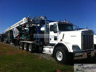
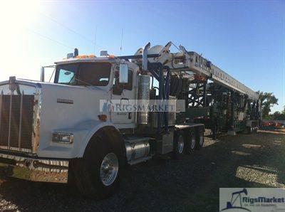
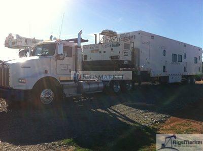
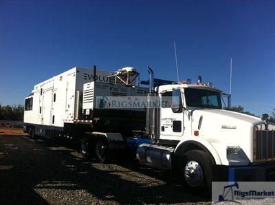
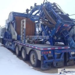
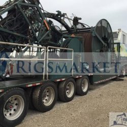
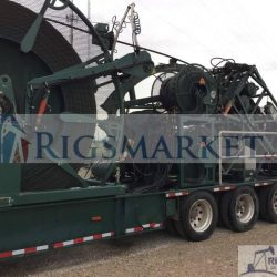
For sale is a used Coiled Tubing Unit For Sale. 80K Injector.
TECHNICAL SPECIFICATION
CTR – Evergreen
Application
The CTR is designed to air drill shallow reservoirs such as coal bed methane up to 3,500 ft deep with coiled tubing. The rig may also be used in coil fracing applications however, it may be limited, as the configuration is most suited to drilling operations. In addition the rig is also capable of running API range 2 or 3 casing and has the ability to drill with conventional pipe by the addition of a top drive. The operating environment for this rig is anticipated to be –40 F to + 104 F* at elevations up to 7,000 ft. The drilling rig is designed in accordance with API recommendation 8C and to a reduced rating of API 4F, being 84 knots (97 mph) from the recommended 97 knots (107 mph).
*Starting of the rig at temperatures below –5 F will require preheating of the hydraulic system.
General
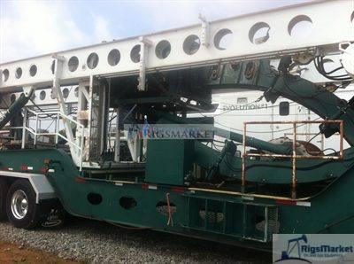
A trailer-mounted coiled tubing rig utilizing a truck equipped with hydraulic wet kit. The trailer rig includes a mast with integral work floor, drawworks, travelling block, storage reel with level wind, injector, and necessary equipment to accommodate an optional top drive. The truck is fitted with a transfer case allowing the truck engine to power the hydraulic system. The rig is designed for drilling applications and includes means for drilling with either coil tubing or jointed pipe in addition to running casing tubulars. The injector is fixed at a set height within the mast. Drilling with jointed pipe or running of casing can be achieved without moving the rig by sliding the injector forward allowing the travelling block and or top drive assembly to pass clear of the injector. All drilling functions can be controlled via the remote control console that is designed for mounting at a remote location. Secondary controls located on the drill unit itself can also be used to operate the drilling functions. Sets up functions are only achieved through controls mounted on the rig trailer.
Height (maximum) 15 ft. with injector retracted – transport mode
Width (maximum) 10 ft. 6”
GVW See Calculations Below
Trailer
Peerless model CH-59-4A perimeter frame design of fabricated T-1 steel with sloped frame rails. Coiled tubing reel to be mounted between rails.
Capacity 90,000 lbs.
Dimensions(approx)64’ 3” overall length
126” overall width
50.9” fifth wheel height – unladen
49.9” fifth wheel height – laden
12” ground clearance minimum (fully laden condition)
Storage reel Mounts to support storage reel pillow block bearings, level wind cylinders, drive
motor and tensioner. Also provide clearance for chain guard, storage reel and hose runs
from tractor.
Gooseneck Weld in SAE 2” king pin
Suspension Quad axle Hendrickson air ride suspension. Rearmost suspension lift-able and pin-able
in raised position. 50” axle spacing.
Axles (4) F22T 25,000 lb rated, Ingersoll axles (10’6” overall width), 16-1/2”x7” Q brakes, rated
22,500 lbs., with type 30/30 air chambers, oil seals, dust shields, Haldex automatic
slack adjusters.
Hubs (8) 10 stud aluminum Unimount hubs, Centrifuse brake drums.
Wheels (16) 10 hole Alcoa aluminum Unimount disc wheels, 8.25 x 22.5
Tires (16) 11R22.5 Goodyear G286, 16 ply tires.
Hydraulic jacks Front & rear outriggers or as required. Includes dual internal counterbalance valves.
Capable of raising both ends of the trailer 24” (42” stroke) in a fully laden condition.
Manual jacks Mechanical landing gear
Mast lift cylinder Provision for mast raise cylinder support
Support
Pick up throat Narrow pick up throat installed.
Air system CMVSS approved air system. Stainless steel wire braided air lines. ABS exempt.
Isolation valve for rearmost axle.
Electrical CMVSS approved. Sealed modular electrical system using Truck-Lite LED lights and
Super Seal wiring harnesses.
Mud flaps/fenders H.D. Black Rubber mud flaps. Anti-sail brackets as required. Aluminum fender above wheels.
Manuals An Owner’s Manual with maintenance procedures & complete parts list of all major
components.
Schematics Air & electrical schematic with parts list.
Rear Bumper Removable – pinned to rear out rigger pads
Truck
See attached specification
Mast
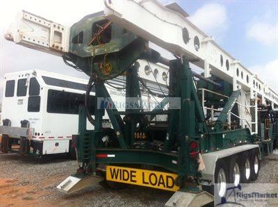
The mast is a steel fabricated twin tube design with raising/lowering from two multi-stage hydraulic cylinders. The mast supports both means of hoisting induced by the injector and casing winch. The mast supports the injector at a fixed height. The injector is attached to a slide mechanism which hydraulically moves the injector to provide clearance for the traveling block and or top drive while hoisting of jointed pipe. The mast also supports a 3-sheave crown block assembly strung with 7/8 inch drill line.
Mast load capacity (Casing) 100,000 lbs.
Mast load capacity (Injector) 80,000 lbs.
Mast casing length capacity API Range III capacity – with topdrive removed (34-48 ft)
API Range II capacity – with topdrive installed (25-34ft)
Mast length based on:
Trailer at laden road height
Top of rotary table bowl – 7’ 6”
Assuming a max. stump height of 24”
Top of stump to top side of elevators 51’
Overall block and bale length (3’ bales) 7’
Top side of block to underside of crown 2’ 10”
Crown sheave assembly Four 20″ diameter sheaves (one sheave fitted with encoder ring)
Travel block Two sheave 50 ton capacity
Crown saver Installed at crown
Counter weight Two 100 lb weights – one on either side of mast. Used to support
manual tong wrenches. Weights are concealed within mast leg with cable strung over crown to work floor.
Injector c/w Mounting Frame & Gooseneck
Make Stewart & Stevenson
Model M 80
Maximum pull* 80,000 lbs.
Snubbing capacity 35,000
Tubing speed* 95 ft/min
Maximum tube size 3 1/2″
Supplied with 3 1/2” gripper blocks
2 7/8” gripper blocks shipped loose
Hook load Double acting load cell mounted in injector frame
Depth counter Encoder driven from planetary
Gooseneck 120” radius. Base of gooseneck is fitted with a mechanical
straightner assembly. A 2 section goose neck folds hydraulically for transport mode. Hydraulic cylinder used to fold gooseneck acts as strut to stabilize and support gooseneck while in
operating mode. Cylinder has provision to provided optional warning of critical out hole tension of storage reel. Hold down rollers (qty. 3) are hydraulically operated. Gooseneck supplied with 3 1/2” roller kit. 2 7/8” roller kit shipped loose. The gooseneck is mounted to a slewing ring that allows the gooseneck to pivot for optimum alignment of coiled tubing to the storage reel. A hydraulic cylinder is used to lock the gooseneck for transport.
Chain/stripper lube system 24 V electrically driven pump and 7 gal storage tank with control to
allow lubrication of either injector chains or stripper assembly.
Frac kit Sling – used to lift the injector from the traversing dolly
Stabilizer bars – used to control movement of the injector caused by
out hole reel tension. Bars are threaded to allow for alignment to
wellhead.
Stripper assembly Suited for 3 1/2” tubing. Hydraulically actuated.
*Note: the above specifications are based on the available hydraulic flow of the provided
hydraulic system.
Storage Reel Assembly
Reel size 144” OD – 114” ID – 66” width This reel shipped loose
Capacity 1,100 m of 2 7/8″ dia. – .190 wall tube*
Reel size 162” OD – 127” ID – 66” width
Capacity 3,000 ft. of 3 1/2″ dia. – .190 wall tube*
Reel mounting Integral with trailer allowing for the storage reel to be recessed between the trailer’s main frame rails.
Drive group Single hydraulic motor with planetary gear reduction designed to hold tension on drum regardless of direction of travel or injector speed. Integral to hydraulic motor drive assembly, fail-safe in line brake (hydraulic pressure required to release brake).
Retention straps Ratchet style winches with nylon straps sufficient to retain storage reel during transport and in the event of drive system failure.
Internal reel plumbing Consisting of ridged 3” – 3000 psi maximum working pressure steel plumbing and hydraulically actuated plug valve. Plumbing is connected from the coiled tubing terminating outside the reel via a blast joint that passes through the reel axle to a point outside the reel, which permits the connection of the drilling fluid/air system. All connections are 1502 style hammer unions.
Note: inside diameters of fittings may be less than 3”.
Minimum diameter not less than 2 5/8”.
3” plug valve A FMC 3” ULT150 3265123 with 1502, controls are located on the remote operators console.
Reel shaft swivel The hydraulic swivel connection is used for activation of the 3” plug valve within the reel.
Level wind Hydraulically driven diamond lead screw. PLC controlled semi
automatic level wind device directs tubing to the enable efficient
placement on the reel as it rotates. A manual override is also provided.
The level wind head is raised/lowered to working position
hydraulically.
Note: *Based on 100% wrap efficiency with no free board. See attached calculations. Calculations are theoretical and capacities will vary.
Top Drive – Provision
The rig is equipped with the necessary hydraulic power source, controls, plumbing and attaching hardware to accommodate a Foremost RC 240 hydraulic top drive assembly. What is not included is the top drive itself consisting of hydraulic motors, gearbox, control valve, mud swivel, carriage, break out tong/guide, bales, elevators and kelly hose.
Top drive performance Maximum Speed – 160 RPM*
Maximum Torque – 10,000 ft/lbs
Note: speed maybe more or less depending on the available HP of the truck engine or other hydraulic requirements. Hydraulic system is designed to accommodate a Foremost model RC 240 top drive, installation of any other model will need to be reviewed and approved by Foremost. Failure to due so will result in termination of any warranties.
Main Drawworks Winch
The drawworks winch is hydraulically driven with a closed loop piston motor circuit through a planetary reduction. Dynamic braking is provided by the hydraulic system.
Capacity 95,000 lbs. (theoretical) with 4-line block (based on a bare drum)
Block speed 200 ft/min. (based on a bare drum)
Brakes Caliper type disc brake (parking)
Hydrostatic braking assisted with caliper disc (service)
Drum capacity 400 ft.
Storage reel capacity 400 ft (for “slip and cut”)
Drive group Hydraulic motor, in-line brake, planetary
Travelling block 50 ton – 2 sheave
Load cell/WOB Load cell clamped to deadline
Winches
Winches are sized for appropriate lift and cable life as per application. The main winch is used primarily for lifting BHA components, drill collars, drill pipe etc from the V-door/catwalk or ground. The secondary winch maybe used for positioning the lubricator assembly over the well.
Main winch – mounted to backside of mast. Cable is strung over the crown and jib assembly as to pull directly in line with well center, side to side, but slightly ahead of well center to the rear. The jib allows to pull to either side of well center, left or right, up to 30 degrees either side of well center.
Capacity 7,250 lbs.
Wire rope 9/16” dia.
Secondary winch – mounted to underside of injector base. Winch is inline with well center, side to side and slightly ahead of well center to the rear.
Capacity 2200 lbs.
Wire rope 3/8” dia.
Doghouse Walkway
Access to the doghouse from the rig substructure is provide via a walkway. A stairway is provide from the substrructure to the trailer deck. A bridge/walkway leads from the trailer deck to the doghouse.
Substructure (Rotary table support)
The main purpose of the substructure is to provide support for the rotary table. The substructure is supported between the mast legs in one of two bolting locations as to suit the height of the work floor at 3 ft or 7 ft 6 in (top of rotary table bowl) positions. The rotary table is used primarily to assist in connecting of jointed components such as the BHA, to the coiled tubing or in the case of operation with the top drive, assist in spinning free tool joint connections. In addition the rotary table bowl can accommodate various sizes of slips necessary to hold back down hole drill strings.
Structure capacity 100,000 lb.
Make-up & Breakout 2 cylinders with cables mounted over a Samson post
Tong wrenches & cables See Tooling list
Work area Steel checker plate and perforated non-slip steel plate
Tong Wrench System
The tong wrench system is mounted to the trailer deck directly behind the substructure floor. The system utilizes two independent hydraulic cylinders with cables necessary to operate manual pipe tongs used in the makeup and breakout of threaded connections. Counterweights are provided to assist in the lifting and lowering of both the makeup and breakout tong wrenches.
Rotary Table
The rotary table’s primary function will be to assist in the makeup and breakout of jointed tubulars quickly and safely.
Rotary table ENID Drill Systems Inc. – Super Bowl
Static weight specs 45,500kg (100,000lbs)
Rotating weight specs 45,500kg (100,000lbs) up to 50 RPM
Dimensions 81cm x 122 cm x 21 cm (32” x 48” x 8 5/8”)
Weight Table – 625 kg (1,400 lbs.)
Bushing – 140 kg (320 lbs.)
Round opening 40.6 cm (16”)
Drive square 46.7 cm (18 ½”)
Drive Hydraulic
Performance 2,250 Nm (1,662 ft/lbs.) @ 125 RPM
Master bushing See Tooling list
Controls
All drilling and casing operations are achieved through remote electrical over hydraulic controls referred to as the Primary System. A redundant Secondary System featuring a combination of electric over hydraulic and manual controls is also provided. The Primary System is designed for remote mounting in the customer supplied control room. The Secondary System is located entirely on the drill rig. A third manual only control system is also supplied and is limited to set up functions such as outriggers, mast raise, gooseneck and hold down rollers and are mounted on the drill rig. A complete set of instrumentation for monitoring rig performance and function such as hydraulic pressures and engine system are included.
Data Acquisition
The data acquisition is the responsibility of the customer however, output sources are provided for the following:
Depth measurement Encoder driven by friction wheel at level wind head
Encoder driven from planetary on injector drive
Segmented crown sheave
Weight on bit – top drive Load cell mounted to deadline of drawworks winch
Weight on bit – injector Load cell mounted below injector drive
Circulation pressure Transducer mounted in plumbing manifold
Engine Display
Caterpillar Driver Information Display (Cat ID) provides visual feedback on engine operating conditions. In addition reports critical or vital fault codes as they happen, and provides a code number and brief description of the fault. This is an add on modular display to be mounted in the main doghouse control panel.
Hook Load
Display for hook load at the travelling block is supplied under the original specification. A load cell attached to the dead line of the drawworks winch is used to provide an electronic signal to an analog style display. The gauge is calibrated to pounds.
Display for hook load and snub load at the injector is supplied under the original specification. A load cell at the injector body is used to provide an electronic signal to an analog style display. The gauge is calibrated to pounds.
Top Drive Torque
Display for top drive torque is supplied under the original specification. A pressure transducer mounted at the forward rotation hydraulic line produces an electronic signal to an analog style gauge. The gauge is calibrated to foot-pounds.
Hydraulic Power Package
Power source Supplied via transfer case installed in truck. See attached specification
for Kenworth T800 highway truck
Transfer case Cushman model 383 with cooler
Injector/drawworks Rexroth closed loop system
Storage reel Rexroth closed loop system
Auxiliary Rexroth open loop system
Hydraulic tank Fabricated steel tank with rubber isolation mounts
Cooler assembly Remote mounted on trailer deck with hydraulically driven fan.
rated at 113 deg F
Hand pump Used to operate front outriggers in absence of wet kit.
Auxiliary hydraulic source to operate customer supplied equipment. 5 section valve bank as per the following:
Sections 1&2 – to operate trash pumps – internally compensated to 15 gpm
Section 3 – to operate power tong – full flow 30 gpm
Sections 4&5 – for future considerations – full flow 30 gpm
Valve bank has no work port reliefs. Individual relief’s maybe required. Sections 3 through 5 will have reduced flow if trash pumps are being operated.
Drill Fluid Plumbing Manifold
A manifold system is provided as a means of connecting the customer supplied air/fluid circulation system to either the coiled tubing storage reel or top drive assembly. A hammer union connection point is provided at the trailer so the remote air/fluid system can be connected. A single gate valve is used to stop the flow two the top drive and a hydraulically actuated plug valve used to stop the flow to the coiled tubing. In general the system will be using air and water as the main drilling fluid and is rated at the following pressures
Maximum operating pressure 3,000 psi
Ridged piping 3”
Top drive – kelly hose 2 ½”
Gate valve 3”
Swivel 3”
Hammer unions 1502
Connection to internal reel plumbing Double Chiksan swivel assembly
Lighting
General rig lighting for night time operation is included. Power will be supplied by the customer.
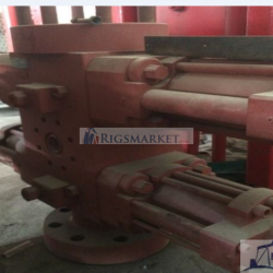
BOP Plumbing
BOP plumbing consisting of quick connectors, hoses and steel piping in order for the customer to connect the BOP stack to the accumulator system (customer supplied). A bulk head is located on the trailer. This bulkhead is equipped with 3 sets of quick couplers suitable in size to connect with the customer supplied accumulator system. All couplers are labeled as to their function. From the bulkhead hydraulic hose is run to a point sufficient in distance from the well center to meet code. At this point steel line (or fire proof hose) is run the length of the trailer to just inside the cellar area at which point it is terminated at a second bulkhead. The purpose of this bulkhead is to allow separate hoses to be run to BOP stack. From bulkhead in the cellar, fire proof hose of sufficient length, complete with quick couplers is supplied to connect with the BOP stack (stack supplied by customer). All hose and fitting sizes, specifications are to be in accordance with applicable codes and customer requirements.
Tooling List
The following items are recommended tools and are not included in the selling price of the rig. This list is subject to change.
Power tongs 1 set suited for 5” casing
1 set suited for 8 5/8” and 9 5/8” casing
Manual tong 2 – Web Wilson (type C ??)
2 sets of jaws for 4” pipe
Bales 1 set of bales – 50 ton – 36” in length – certified
Elevators 1 set suited for 5” casing
1 set suited for 8 5/8” casing
1 set suited for 9 5/8” casing
Slips All slips to fit internal API opening 13 1/16” top of taper with 4” TPF
1 set suited for 4” pipe
1 set suited for 5” casing
1 set suited for 8 5/8” casing
1 set suited for 9 5/8” casing
Master Bushing 46.7 cm (18 ½”) square drive. Internal API opening 13 1/16” top of taper with
for Rotary Table 4” TPF
Top Drive Kit – Foremost Model 240
The following items are not included in the selling price of the rig and are subject to change.
Model 240 Top Drive
• Maximum RPM – 230 *
• Maximum Torque – 20,000 ft/lbs*
• Maximum Hoist Load – 200,000 lbs (rotating)
• Spindle Opening – 3”thru bore with 6 5/8 API regular box
• Reduction – 5:1
*The above specifications are theoretical maximums and are subject to the hydraulic input provided. See below.
10,000 ft/lb Motor Group (215 kW (288 HP) 34,450 kPa (5000 psi) @ 375 l/min (99 gal/min) input required for maximum performance)
• Utilizing two Rexroth fixed displacement motors:
Speed range variable: 0 – 160 rpm
Torque capacity variable 0 – 14,000 Nm (0 – 10,300 ft lbs.)
Two Sheave Split Travelling Block c/w Guides
• Qty 2 – 50.8 cm (20”) diameter sheaves for 22 mm (7/8”) cable
• Hoisting capacity – 45,400 kg (100,000 lbs)
• Qty 2 – guide assemblies with nylon inserts to suit tube rails on inside of derrick legs. Guide assemblies keep top drive aligned to well center and transfer top drive torque top derrick legs.
Bales and Elevators
• Bales and Elevators are to be supplied by the customer at their expense
• Two hydraulic cylinders are mounted below the top drive that can be connected to the bales. These cylinders allow for the bales with elevator to be hydraulically positioned towards the v-door to connect to the drill pipe.
Mud Swivel Assembly
• 76.2 mm (3 in) mud inlet swivel mounted directly to top drive. Rated at 31,000 kpa (4500 psi) working pressure.
• 76.mm (3 in) goose neck to support kelly hose.
Spindle Brake
• Hydraulically actuated pinion disk brake to positively lock top drive
0 – 14,000 Nm (0 – 10,300 ft lbs.) backup capacity
Floating Cushion Sub
• Floating cushion sub provides a telescopic action that minimizes axial loading while making or breaking tool joints.
• Box and pin connections are cut to customers specifications
• 6 5/8 API reg X customer specified thread crossover sub to connect with floating cushion sub
Hydraulic Back-up Tong
• Hydraulically actuated tong assembly mounted below top drive to assist in breakout/ make-up of the drill string.
Hose Kit
• All necessary hydraulic hoses necessary to connect top drive to rig. Includes kelly hose and electric control cable
Coiled Tubing Reel Capacity
(based on 100% reeling efficiency less one wrap)
Tubing Specifications
OD: 2.88 ” 73.025 mm
Wall: 0.188 ” 4.78 mm No interweaving of the wraps is
Weight: 5.395 lb/ft 8.03 kg/m considered.
Volume: 6.07 bbl/1,000 ft 3.16 m3/1,000 m
Minimum
Reel Dimensions Recomended Core Diameters
1.25″ – 72″ diameter core
ID: 127.00 ” 3.23 m (Actual reel drum dia.) 1.50″ – 84″ diameter core
OD: 162.00 ” 4.11 m (Actual reel outside dia.) 1.75″ – 90″ diameter core
Width: 66.00 ” 1.68 m (Actual reel inside width) 2.00″ – 96″ diameter core
2.38″ – 100″ diameter core
Wrap Wrap D. Wrap L. Total L. Total Wt. Capacity Total L. Total Wt. Capacity 2.88″ – 110″ diameter core
No. (in) (ft) (ft) (lb) (bbl) (m) (kg) (m3)
1 129.875 748 748 4,036 4.5 228 1,830 0.72
2 135.625 781 1,529 8,250 9.3 466 3,742 1.47
3 141.375 814 2,343 12,643 14.2 714 5,734 2.26
4 147.125 847 3,191 17,215 19.4 973 7,807 3.08
5 152.875 880 4,071 21,965 24.7 1,241 9,962 3.93
6 158.625 914 4,985 26,894 30.2 1,519 12,197 4.81
7 0 0 0 0 0.0 0 0 0.00
Coiled Tubing Reel Capacity
(based on 100% reeling efficiency less one wrap)
Tubing Specifications
OD: 3.50 ” 88.9 mm
Wall: 0.188 ” 4.78 mm No interweaving is
Weight: 6.650 lb/ft 9.89 kg/m considered.
Volume: 9.48 bbl/1,000 ft 4.95 m3/1,000 m
Minimum
Reel Dimensions Recomended Core Diameters
1.25″ – 72″ diameter core
ID: 127.00 ” 3.23 m (Actual reel drum dia.) 1.50″ – 84″ diameter core
OD: 162.00 ” 4.11 m (Actual reel outside dia.) 1.75″ – 90″ diameter core
Width: 66.00 ” 1.68 m (Actual reel inside width) 2.00″ – 96″ diameter core
2.38″ – 100″ diameter core
Wrap Wrap D. Wrap L. *Total L. Total Wt. Capacity Total L. Total Wt. Capacity 2.88″ – 110″ diameter core
No. (in) (ft) (ft) (lb) (bbl) (m) (kg) (m3) 3.50″ – 140″
diameter core
1 130.5 615 615 4,090 5.8 187 1,855 0.93
2 137.5 648 1,263 8,399 12.0 385 3,809 1.90
3 144.5 681 1,944 12,927 18.4 592 5,862 2.93
4 151.5 714 2,658 17,674 25.2 810 8,016 4.01
5 158.5 747 3,405 22,641 32.3 1,038 10,268 5.13
6 0 0 0 0 0.0 0 0 0.00
*Total length is theoretical, actual capacity will vary.
AXLE WEIGHT CALCULATION FOR EVERGREEN CTR
AXLE TO KINGPIN DIST (IN) 605
TRAILER KINGPIN (TARE) (LB) 6985
TRAILER AXLE (TARE) (LB) 17435
ITEM WEIGHT (LB) LOCATION (IN) TRAILER TRAILER AXLE
FROM REAR AXLE KING PIN WT (LB) WT (LB)
TRAILER ADDITIONS LESS MAST REST 4689 80 620 4069
Mast 19207 219 6953 12254
Storage Reel 12032 435 8651 3381
Tubing 20000 435 14380 5620
Winch 5100 256 2158 2942
Injector 12893 181 3857 9036
DRILLING FLOOR 1632 -149 -402 2034
Mast Rest 408 538 363 45
Mast Raise Cyls 1632 0 0 1632
Tong Cyls And Tools 1020 8 13 1007
Travelling block, links and elevators 1632 -41 -111 1743
Front outriggers 1704 350 986 718
Rear outriggers 1704 -120 -338 2042
Rotary table (new) 1224 -149 -301 1525
Auxilliary winch’s 735 123 149 586
Hyd hosing and misc 8595 229 3253 5342
Air Plumbing Assy 1245 340 700 545
HYD OIL 510 220 185 325
TRAILER PAYLOAD TOTALS (LB) 41117 54845
TRAILER KINGPIN (GVW) (LB) 48102
TRAILER REAR AXLE (GVW) (LB) 72280

